Topographical Geolocation: Triangulating Mountain Ridges, Digital Elevation Models, and Horizon Lines
How to geolocate photos and videos in remote, rural landscapes devoid of street furniture: matching horizon silhouettes against Digital Elevation Models (DEM), 3D viewpoints, and solar azimuth arcs.
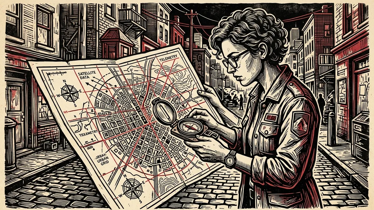
In urban environments, open-source researchers routinely rely on street furniture, commercial storefronts, traffic lights, and utility poles to pinpoint coordinates on Google Street View.
However, in vast conflict zones—such as the Hindu Kush of Afghanistan, the Zagros Mountains of Iran, the high Caucasus, or the stepped plains of Central Asia—investigators are confronted with barren, rural vistas containing no human-built infrastructure whatsoever. A convoy moves along an unpaved dirt track flanked by jagged peaks; an armed militia records a propaganda video in a desolate mountain valley; a missile test impacts in a rocky desert.
When traditional geospatial reference markers are absent, the Earth’s topography itself provides an indelible, mathematically unique fingerprint.
Because tectonic mountain ridgelines, saddle depressions, and elevation gradients remain immutable over centuries, researchers can match the photographic horizon line against planetary Digital Elevation Models (DEM).
This field guide provides an end-to-end technical methodology for extracting horizon silhouettes, calculating camera focal length fields of view, and running synthetic 3D viewshed simulations to pinpoint coordinates in rural conflict zones.
1. The Physics of Perspective: Field of View and Focal Length
Before attempting to match a distant mountain ridge, an investigator must understand the optical perspective of the camera lens that recorded the image.
                              CAMERA OPTICAL CONE
                                      /
                                     /
             ┌──────────┐           /
             │  CAMERA  │ ─────────► [OPTICAL AXIS / HORIZON SILHOUETTE]
             └──────────┘           \
                                     \
                                      \
                                 [FIELD OF VIEW (FOV)]
The Compression Effect of Telephoto Lenses
Smartphone wide-angle cameras and telephoto surveillance cameras depict mountains in completely distinct ways: * Wide-Angle (24mm–28mm equivalent): Mountains appear small, distant, and flat; valleys between peaks seem exaggeratedly broad. * Telephoto / Zoom (100mm–300mm+ equivalent): Optical compression flattens distance. Distant mountain peaks appear stacked tightly directly behind foreground hills, compressing horizontal space.
Calculating the Horizontal Field of View ($HFOV$)
If the original camera EXIF metadata is preserved, calculate the horizontal field of view ($\alpha$) using the 35mm equivalent focal length ($f$): $$\alpha = 2 \times \arctan\left(\frac{36}{2f}\right) \times \left(\frac{180}{\pi}\right)$$
| 35mm Equivalent Focal Length ($f$) | Horizontal Field of View ($\alpha$) | Typical Source Device |
|---|---|---|
| 24 mm | $73.7^\circ$ | Smartphone primary wide lens |
| 50 mm | $39.6^\circ$ | Standard human-perspective prime lens |
| 120 mm | $17.1^\circ$ | 3x to 5x smartphone telephoto / drone zoom |
| 300 mm | $6.9^\circ$ | High-magnification reconnaissance lens |
If EXIF data is stripped (as is standard on social media), look for secondary perspective cues: if foreground objects are in sharp focus while distant peaks appear hazy without apparent perspective divergence, assume a narrow telephoto cone ($10^\circ \text{ to } 25^\circ$).
2. Extracting the “Horizon Silhouette Vector”
To compare an image against planetary elevation models, investigators isolate the high-contrast boundary where mountain rock meets the sky.
ORIGINAL IMAGE:
  [SKY]
  ▲ ▲ ▲ ▲ ▲ ▲ ▲ ▲ ▲ ▲ ▲ ▲ ▲ ▲ ▲ ▲ ▲ ▲ ▲ ▲ ▲ ▲ ▲ ▲ ▲ ▲ ▲
  ┌───────────────────────────────────────────────────┐
  │         /\                                        │
  │        /  \   /\                  /\              │  <-- PRIMARY RIDGE (SILHOUETTE)
  │       /    \_/  \                /  \/\           │
  │      /           \/\            /      \          │  <-- INTERMEDIATE RIDGE
  │  ___/               \__________/        \______   │
  └───────────────────────────────────────────────────┘

EXTRACTED VECTOR TRACE:
  ───/\──────/\──────────/\─────────/\──────/\/\──────
The Trace Methodology
- Open the image in an image editing program (Photoshop, GIMP) and boost contrast to exaggerate the skyline boundary.
- Using a high-contrast brush or vector path tool, draw a crisp 1-pixel red or black line following the crest of the highest mountain ridgeline from left to right.
- Draw secondary dashed lines tracing visible intermediate ridgelines (hills in the middle ground that overlap foreground terrain).
- Note key topographic anomalies:
- Sharp Glacial Horns: Acute needle-like peaks indicating high-altitude granite formations.
- Saddles & Cols: U-shaped or V-shaped depressions between paired summits.
- Plateau Steps: Flat horizontal mesas indicating sedimentary basalt strata.
3. Digital Elevation Models (DEM) and Peakfinder Tools
A Digital Elevation Model (DEM) is a raster grid of the Earth’s surface where each pixel contains a precise altitude value above sea level. Major global datasets include: * SRTM (Shuttle Radar Topography Mission): 30-meter global resolution. * Copernicus DEM (GLO-30): High-accuracy 30-meter global elevation model compiled by the European Space Agency. * ALOS World 3D (AW3D30): 30-meter model derived from Japan’s PRISM stereo optical satellite.
                    TERRAIN SIMULATION WORKFLOW
                                 │
     ┌───────────────────────────┴───────────────────────────┐
     ▼                                                       ▼
PEAKFINDER.ORG (FAST SCAN)                              BLENDER-GIS / QGIS (DEEP 3D)
• Ingests global DEM                                    • Ingests 30m / 10m DEM rasters
• Renders 360° wireframe silhouette                     • Precise focal length & camera altitude
• Move camera coordinates in 100m steps                 • Overlay drone footage directly onto mesh
• Displays true azimuth to each named peak              • Defensible millimeter ray-casting proof
Rapid Reconnaissance via PeakFinder
- Navigate to PeakFinder.org (or equivalent web elevation renderers).
- Drop an initial estimated pin in candidate mountain valleys identified through regional intelligence or flight path constraints.
- Adjust the simulated camera view direction (azimuth) and field of view ($HFOV$) to match the focal length calculated in Step 1.
- Align the peaks: as the digital camera point moves across the map, watch how the parallax between foreground hills and background mountains shifts.
- When the wireframe peaks, cols, and intermediate slope angles match the photographic silhouette perfectly across a $40^\circ$ panorama, the camera location is constrained to within a few hundred meters.
4. Advanced 3D Ray-Casting in Blender-GIS and Google Earth
For definitive judicial reports, web-based tools provide insufficient precision. Forensic teams construct full 3D virtual environments to align camera perspectives mathematically:
[INVESTIGATIVE PHOTO] ──► [IMPORT 30M DEM RASTER] ──► [CONSTRUCT 3D CAMERA] ──► [OVERLAY OPACITY]
                                                            • Set focal length (mm)     • 0% to 100% slider
                                                            • Altitude above ground     • Perfect wireframe
                                                            • Heading, pitch, & roll      boundary lock
- Import DEM into Blender via Blender-GIS: Download the 30-meter Copernicus DEM tile covering the suspected operational sector and convert it into a 3D polygonal terrain mesh.
- Recreate Camera Optics: In Blender’s camera settings, set the exact sensor size (e.g., 36mm $\times$ 24mm full-frame) and the focal length ($f$).
- Ray-Casting the Line of Sight:
- If two distinctive peaks are visible behind a foreground ridge, their alignment creates an unambiguous mathematical line of sight.
- Sighting through the foreground hill summit to the background mountain peak defines a vector: $$\vec{V} = \vec{P}{\text{background}} - \vec{P}$$}
- The camera must physically lie along the reverse trajectory of this vector line on the terrain.
- Intersect with Road Grids: Intersect the calculated sight-line vector with unpaved road tracks visible on high-resolution satellite imagery (Sentinel-2, Google Earth). The camera coordinate is locked at the exact intersection where a vehicle could navigate.
5. Integrating Solar Azimuth Chronolocation
Topographical triangulation provides spatial coordinates ($X, Y$); solar physics adds temporal verification ($Z$ time):
- Once candidate mountain peaks are identified, determine their compass orientation (e.g., Peak Alpha is located at True Azimuth $142^\circ$ Southeast).
- Inspect the sunlight and shadow boundary on the mountain face:
- Are the western slopes illuminated while eastern canyons lie in deep shadow?
- If the western face is illuminated, the photograph was recorded in the late afternoon.
- Cross-reference shadow angles against client-side ephemeris calculators (such as the Dawat Solar Chronolocator) to eliminate invalid seasons or hours.
By treating the Earth’s jagged horizon as a permanent fingerprint, researchers prove that even in the most desolate, infrastructure-free terrains on Earth, covert actors cannot hide their operational coordinates.
How to Geolocate Rural Photos Using Mountain Horizons and Digital Elevation Models
Methodology for pinpointing coordinates in barren landscapes by matching horizon silhouettes against Digital Elevation Models (DEM).
- Extract the Skyline Silhouette Vector: Trace the high-contrast boundary line where mountain peaks and saddle depressions meet the sky.
- Calculate Camera Horizontal Field of View (HFOV): Determine optical perspective and focal length from EXIF metadata or foreground telephoto compression cues.
- Simulate 3D Viewpoints in PeakFinder or Blender-GIS: Compare photographic silhouette traces against 30-meter Copernicus DEM elevation wireframes.
- Triangulate Solar Azimuth Angles: Inspect mountain slope lighting and shadow vectors to eliminate invalid compass orientations and verify time of day.
Frequently Asked Verification Questions
Key technical principles, error traps, and diagnostic standards for investigative researchers.
How can you geolocate an image in a barren desert with no buildings or roads?
What is a Digital Elevation Model (DEM) and how does it help OSINT investigations?
Simulate Sun Arcs & Inspect Geotag Metadata
Calculate solar azimuths on mountain slopes to verify time-of-day, and extract hidden EXIF camera focal lengths in private memory.
About the Contributor
The Dawat Forensic Research Desk specializes in open-source investigative intelligence, conflict zone media verification, and digital human rights documentation.
Related Research & Dispatches

Radio Frequency Direction Finding: Principles of Signal Triangulation and Spectrum Monitoring for Field OSINT
How open-source investigators and field journalists leverage Software-Defined Radios (SDR), directional antenn...
Scraping and Archiving Telegram War Channels: Preserving Evidentiary Chains of Custody Before Takedowns
A technical blueprint for extracting, hashing, and preserving digital media, message histories, and user metad...
Verifying FPV Drone Strike Footage: HUD Telemetry Decoding, Electronic Warfare Jamming, and Impact Geolocation
A forensic framework for authenticating First-Person View (FPV) kamikaze drone strikes: extracting On-Screen D...